Part I. Team Member
| Name | SID | |
|---|---|---|
| GuTao | - |
Part II. System Function
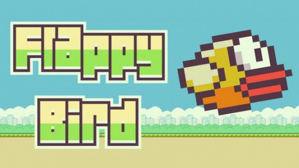
In this project, I designed a game based on the VGA module of EGO1 development board using Verilog to imitate Flappy Bird. In the project, the player can press the button to control the bird to jump upward through the gap of the tubes to score points.
The project implements basic user interaction interface, start, pause, reset and other game functions, and also adds new features such as highest score, difficulty switch, developer mode etc. to provide a more comfortable player experience while ensuring a high degree of reproduction.
Part III. System Design
Working principle
(a) Connect the monitor and press the global RESET button, the monitor displays 640*480 game screen, at this time the bird is stationary and the tube is on the right side out of the screen.
(b) After selecting the DIFFICULTY by the switches the game starts, the bird will start moving under the simulated gravity and FLAP button, while tubes of random heights are generated from the right side of the screen and move to the left, the FLAP button supports “short press short jump” and “long press continuous flight” function.
(c) The player will get a point after operating the bird through a tube. The four LED SEGMENT DISPLAYS on the right side show the current score and the other four show the highest score, and the highest score will be updated automatically when the score breaks the record.
- (d) The game ends when the bird collides with the water tube or the ground, the bird lands at a constant speed, the tubes stop moving, the FLAP button and DIFFICULTY switches are disabled, and the GAMEOVER LED lights up.
- (e) After game over, switch the difficulty to 0, press the RESTART button and select the difficulty and restart the game. The high score will be kept when the EGO1 development board is not disconnected. The game can be paused by setting the difficulty to 0 during the game.
- (f) The rightmost small switch is set to DEVELOPER MODE, which is used to observe the game difficulty and debug features. When turned on, the DEVELOPER MODE LED lights up and the bird will be stripped from the tube layer to a higher dimension and fly over the side of the tube without causing game over.
- (g) The game supports hot-swapping for both 640480 and 800600 resolutions, and will generate maps of suitable difficulty adapting to different resolutions.
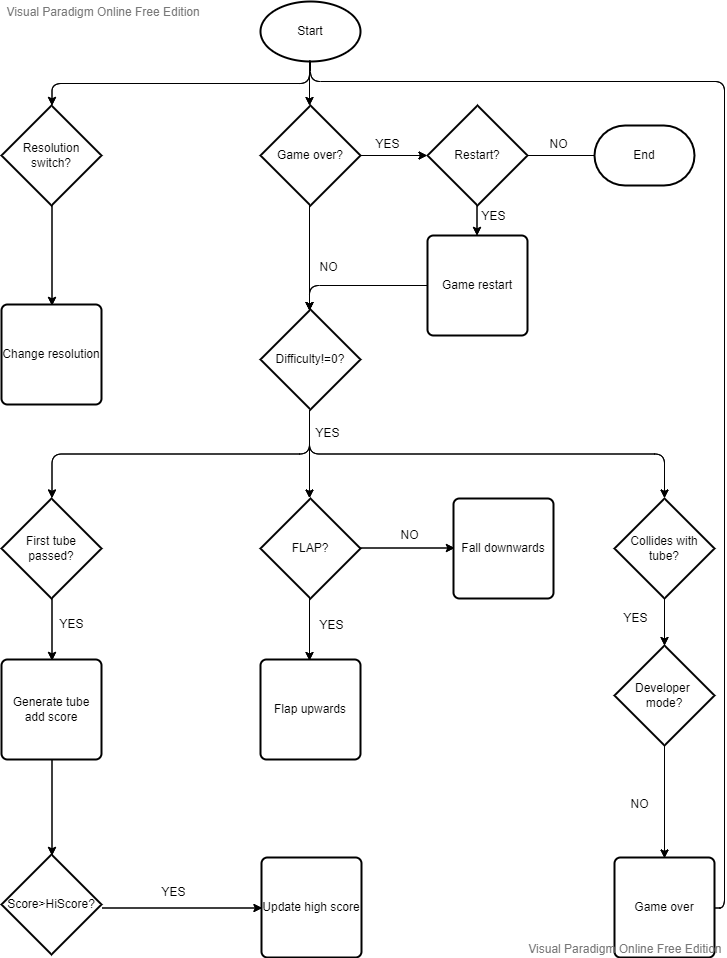
System work flow chart

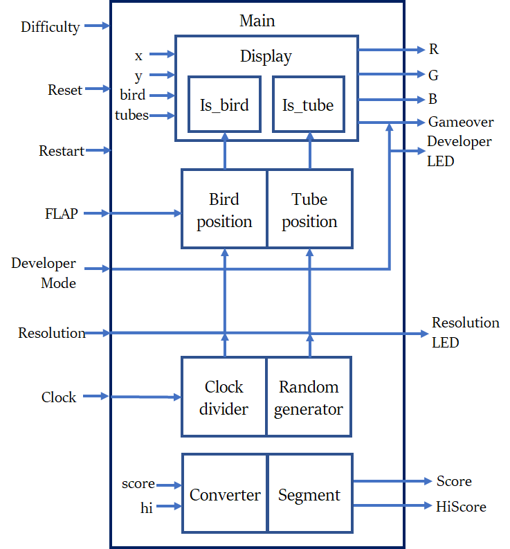
System frame diagram

Port logic function description
| Port | Direction | Width(bit) | Function Description |
|---|---|---|---|
| R | OUT | 4 | Red signal for VGA |
| G | OUT | 4 | Green signal for VGA |
| B | OUT | 4 | Blue signal for VGA |
| hsync | OUT | 1 | Horizontal sync signal |
| vsync | OUT | 1 | Vertical sync signal |
| cho | OUT | 8 | Sequence of chosen segment |
| lseg | OUT | 8 | Left segment |
| rseg | OUT | 8 | Right segmet |
| overled | OUT | 1 | Gameover LED |
| stateled | OUT | 1 | Resolution mode LED |
| cheatled | OUT | 1 | Developer mode LED |
| rst | IN | 1 | Refresh displayer |
| restart | IN | 1 | Reset game |
| flap | IN | 1 | Flap button |
| reso | IN | 1 | Resolution switch |
| cheatmode | IN | 1 | Developer mode switch |
| clk | IN | 1 | Default clock |
| sw | IN | 3 | Difficulty switches (0 for pause) |
Sub-module design
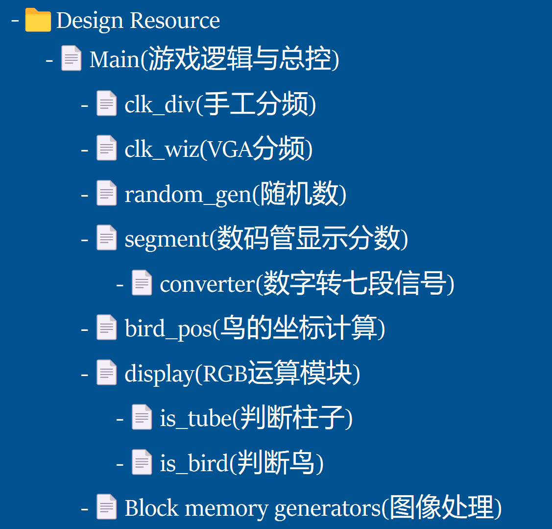
The system is divided into 11 sub-modules, the relation between modules are shown as follows.

(a) Main module
The master control module, which integrates each sub-module, gets the clock signal, LED segment signal, coordinate information, and is also responsible for the output of VGA display signal, game difficulty selection, game over judgment, restarting the game, switching resolution, etc. It is the integrated module of all input ports and output ports.
(b) Clock divider & clock wizard module
Frequency divider module, the game clock frequency is manually implemented, 100MHz clock frequency of EGO1 reduced by two million times to get 50Hz of the game clock frequency, the logic of the manual frequency divider is: the use of counter
t%2000000 = 0condition output 1ns high level game clock and clear the counter. The clock wizard IP core is used to obtain the VGA synchronous clock frequency divider in two resolutions, 640*480 corresponds to 25.175MHz, 800*600 corresponds to 40MHz.
(c) Random generator module
Retrieved from the answer of @nguthrie on stackoverflow: how to implement a pseudo hardware random number generator?
(d) Segment & Converter module
The converter module is responsible for converting the input decimal score into BCD code, and then outputting the segment sequence according to the parameter table.
The segment display module is responsible for reading the sequence from the converter module, and displaying the highest score and the current score on the eight-digit eight-segment display by dividing the frequency.
(e) Bird position module
The bird position calculation module is responsible for processing the input current y coordinate and the FLAP button information and obtaining the y coordinate of next frame. When the FLAP button is pressed, the bird is given an upward initial velocity, otherwise the bird is subjected to a downward simulated gravitational acceleration. The coordinate is calculated using a right shift operation for fluency, which simulates float calculation and gravity.
(f) Display module (is_bird & is_tube module)
The display module is responsible for processing the input query coordinates and the position information of each element, and outputting the color information corresponding to the query coordinates. The display priority of the same coordinates: bird > tube > background.
is_birdandis_tubemodules pass their relative coordinates to the top leftmost pixel for the input coordinates, and use theBlock Memory GeneratorIP core in the display module to take out the corresponding color values and output the color of the current query position after deciding the priority.(g) Block Memory Generator
This project uses this IP core to connect
bird.coe,tube_body.coe,tube_head.coe,bg.coeto display images of birds, tube, and backgrounds.
Simulation result (waveforms)
* As some of the modules have tons of input and output ports and are quite complex, simulation steps are not used in the development process, so the part of the waveforms are not shown here.
(a) Converter simulation

(b) Random generator simulation

(c) Clock divider module (Mod factor shrunk for better simulation)

(d) Segment module (Higher shifting frequency for better simulation)

Part IV. Problems encountered and solved
Question1. How to display the image instead of simply rectangles and squares?
Reason: The very first step during my development process is to protect my eyes, a better UI is more comfortable for development, so implementing images is my first step.
Solution: Block memory generator, read the help document and seek help from my friend. By the way, the first time I displayed the game, the color was quite strange (red cloud, purple tube etc.), and that’s because the non-active part of the screen was unexpectedly assigned with non-zero values, and the screen took these values as noise and subtracted them from normal values, leading to the strange color shift.
Question2. How to generate tubes of random height?
Reason: To add some basic difficulty to this game.
Solution: Seek help from _stackoverflow_, this pseudo 5-bit random number generator is powerful enough for my project.
Question3. How to create map adapting to different resolutions?
Reason: Some classmates encounter problem when switching to a higher resolution, so I want to solve it before it happens.
Solution: Use screen height and screen width as parameter to generate map instead of using constant, which guarantees the tube height and tube generation interval to automatically fit the resolution.
Question4. How to simulate the gravity?
Reason: To make the flap and fall more fluent and natural.
Solution: Use right shift operation to simulate the float calculation, introduce velocity and acceleration to calculate the bird position, and update it at the frequency of 50Hz.
Question5. How to judge game over? / How to figure out the priority of elements when displaying?
Reason: To optimize the visual experience, when bird hits the tube, it should fall slowly to the ground, which may cause the bird to have intersection with the tube.
Solution: Bird>Tube>Background, also some pixels of bird is transparent, for these pixels I need to display the tube or background below the bird. Also, the logic of judging game over is quite simple using display logic, that is, when a pixel tries to display both bird and tube, it means that the bird has hit the tube, game over.
Part V. Summary & experience
* Since my English level is not so high, I use Chinese here to better express my true feeling :)
本次项目我利用本学期所学知识,基于EGO1开发板使用Verilog复现了经典小游戏Flappy Bird,项目中熟悉了VGA显示原理、数码管显示原理、状态机的转移和设计、简单游戏逻辑设计、硬件语言开发流程等内容。
特别感谢肖佳辰等同学提供了若干踩坑的经验,开发过程中预防了很多问题,整个开发过程实际用时不到24h,不过我在开发过程中还是遇到了花式的问题和困难,但最终也都得到了不错的解决。同时我也为其他同学提供了多次帮助,例如屏外噪声、图像导入、分辨率切换、游戏逻辑等问题。
项目中最大的收获是模块化设计的思想,本次开发前我先在纸上设计好了各个模块的大致功能和模块间互相调用的关系,在实际开发时按部就班达到了很高的效率,比较java项目边写边加的模式更为从容有条理。
实际上,本次项目由于开发周期短(同期的数据库项目对时间占用较大)还存在较多的不足,在本学期课程结束后我会将GitHub上的项目同步并继续开发,优化界面、调整重力等参数,因为我对本项目抱有较大的兴趣,所以我会继续做下去。
报告的最后,非常感谢为本学期课程和项目提供指导帮助的老师、助教和图班优秀的同学们,让我从一个对硬件一无所知甚至抱有胆怯的小白变成了对硬件编程、电路设计感兴趣的人,受益匪浅。