$\huge\text{Outline}$
- Pipelining
- Memory Hierarchy
- Parallel Processors
Chapter 4 - Piplining
§4.1 Pipeline Overview
Performance Issues:
- Longest delay determines clock period
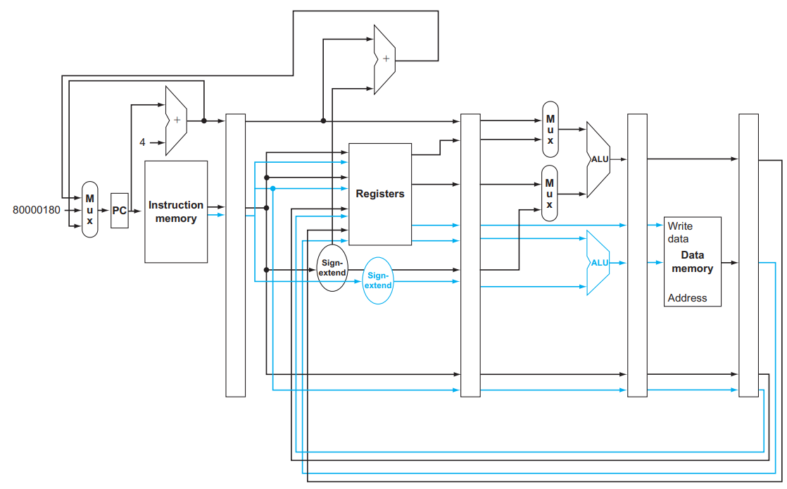
- Critical path: load instruction
- Instruction memory → register file → ALU → data memory → register file
- Not feasible to vary period for different instructions
- Violates design principle: Making the common case fast
Pipeline:
An implementation technique in which multiple instructions are overlapped in execution. Reduces time between instructions.
Pipeline is a form of parallelism.
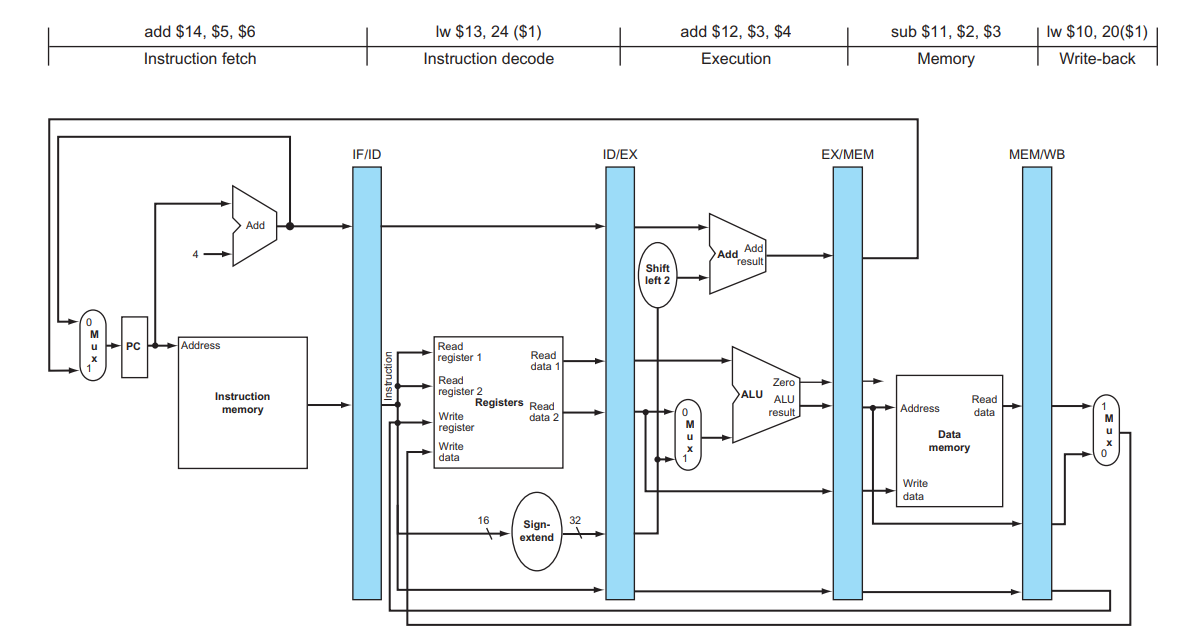
5-stage pipeline:
- IF: Instruction fetch from memory
- ID: Instruction decode & register read
- EX: Execute operation or calculate address
- MEM: Access memory operand
- WB: Write result back to register
Pipeline Speedup:
If all stages are balanced (take the same time),
* here $\text T$ means time between instructions.
If not balanced, speedup is less.
- Latency (time for each instruction) does not decrease
§4.2 Hazards
Structure hazards:
Conflict for use of a resource.
If data and instructions all in one, accessing DATA MEM and INST MEM will cause a pipeline “bubble”.
Data Hazards:
Need to wait for previous instruction to complete its data read/write.
use-use hazard, load-use data hazard
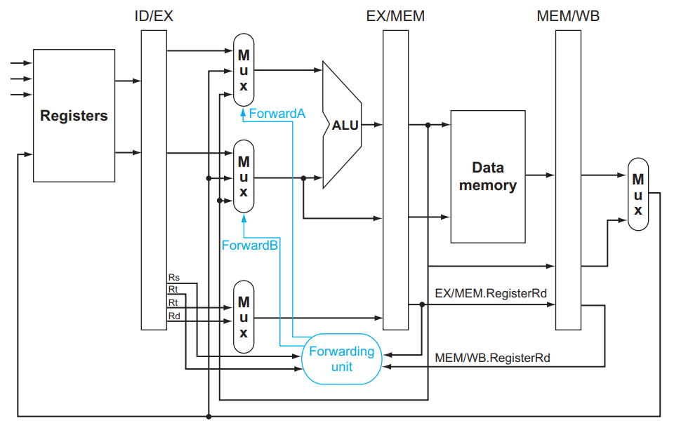
Forwarding:
Use result immediately when it is computed.
- Don’t wait for it to be stored in a register
- Requires extra connections in the datapath
- Add a bypassing line to connect the output of EX to the input
- EXE - EXE
- MEM -EXE
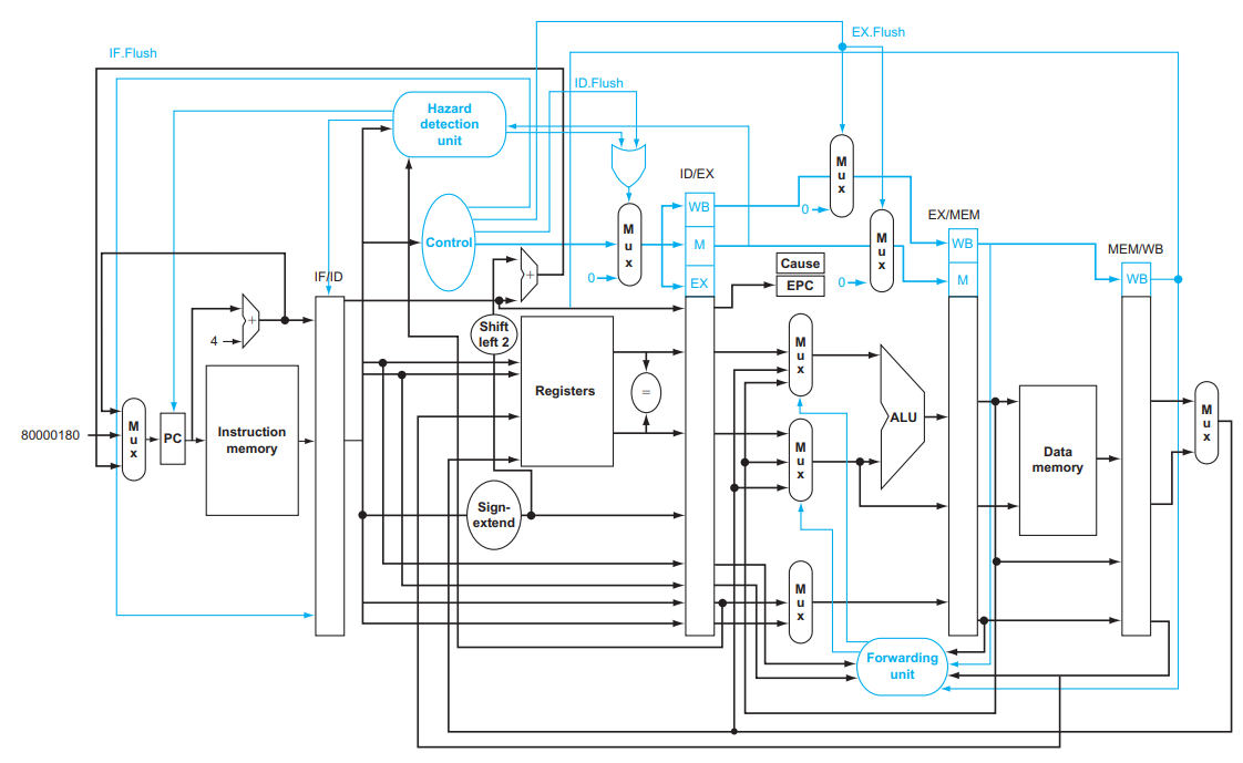
Control Hazards:
Fetching next instruction depends on branch outcome.
In MIPS pipeline,
Need to compare registers and compute target early in the pipeline.
Add hardware to do it in ID stage.
Branch Prediction:
Predict outcome of branch, stall only if prediction is wrong.
Static branch prediction
Done by compiler(software)
Dynamic branch prediction
Hardware measures actual branch behavior, e.g., record recent history of each branch. Assume future behavior will continue the trend.
§4.3 Instruction-level Parallelism
To increase Instruction-level parallelism(ILP):
Deeper pipeline: more stages
Less work per stage → shorter clock cycle
Multiple issue: start multiple instructions per clock cycle
Instruction per Cycle: $\text{IPC}={1\over \text{CPI}}$
More hardware used
Key problems of multiple issue:
- Packaging instructions into issue slots
- Dealing with data and control hazards
| $\text{Multiple issue type}$ | Static multiple issue | Dynamic multiple issue |
|---|---|---|
| Also called | Very long instruction word (VLIW) | Superscaler |
| Decision made by | Compiler (software) | Processor (hardware) |
| Ways to remove hazard | Loop unrolling/ Register renaming | Out-of-order execution |
Static multiple issue
- Decision made by compiler, software
- Compiler groups instructions into “issue packet”
- Group of instructions that can be issued on a single cycle
- Determined by pipeline resources required
- Think of an issue packet as a very long instruction
- Specifies multiple concurrent operations
- Very Long Instruction Word (VLIW)
MIPS with Static Dual Issue:
Two-issue packets
- Type 1: ALU or branch instructions
- Type 2: load or store instructions
Hazards
- Split interdependent instructions into different packet
- Put bubbles: one stall, multiple instructions wait.
Scheduling:
1 | lw $t0, 0($s1) # $t0=array element |
| ALU/branch | Load/store | cycle |
|---|---|---|
nop |
lw $t0, 0($s1) |
1 |
addi $s1, $s1,–4 |
nop |
2 |
addu $t0, $t0, $s2 |
nop |
3 |
bne $s1, $zero, Loop |
sw $t0, 4($s1) |
4 |
Loop Unrolling:
- Remove “name dependence”
- Replicate loop body to expose more parallelism
- Register renaming: use different registers per replication
- Reduces loop-control overhead
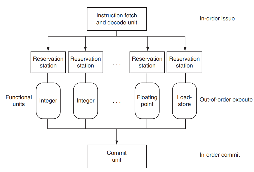
Dynamic multiple issue(Superscalar)
- Decision made by processor during execution
- CPU decides whether to issue 0, 1, 2, … each cycle,avoiding structural and data hazards
- Hardware support for reordering the order of instruction execution
- Allow the CPU to execute instructions out of order to avoid stalls
- Commit result to registers in order
Speculation
“Guess” what to do with an instruction:
- Start operation as soon as possible
- Check whether guess was right
- If so, complete the operation
- If not, roll-back and do the right thing
Compiler/Hardware Speculation:
- Compiler can reorder instructions
- Can include “fix-up” instructions to recover from incorrect guess
- Hardware can look ahead for instructions to execute
- Buffer results until it determines they are actually needed
- Flush buffers on incorrect speculation
Speculation and Exceptions:
Static speculation: Can add ISA support for deferring exceptions
Dynamic speculation: Can buffer exceptions until instruction completion (which may not occur)
§4.4 Fallacies, Pitfalls and Summary
Fallacies & Pitfalls
The basic idea of pipelining is easy, the devil is in the details.
More transistors make more advanced techniques feasible, pipeline-related ISA design needs to take account of technology trends.
Poor ISA design can make pipelining harder
Summary
ISA influences design of datapath and control
Datapath and control influence design of ISA
Pipelining improves instruction throughput using parallelism
- More instructions completed per second
- Latency for each instruction not reduced
Hazards: structural, data, control
Multiple issue and dynamic scheduling (ILP)
- Dependencies limit achievable parallelism
- Complexity leads to the power wall
Chapter 5 - Memory Hierarchy
§5.1 Introduction
Larger, Slower, Cheaper: Register → L1 Cache → L2 Cache → Memory → Disk
Cache (CPU←→Memory)
Virtual Memory (Memory←→Disk)
DRAM: high bit density, but relatively poor latency
SRAM: faster, but lower bit density
Memory Hierarchy:
- Store everything on disk
- Copy recently accessed (and nearby) items from disk to DRAM (main memory)
- Copy recently accessed (and nearby) items from DRAM to SRAM (cache memory attached to CPU)
If accessed data is absent in upper level: miss and block(copy)
If accessed data is present in upper level: hit
Locality makes caches work
- Temporal locality: possible to access items again
- Spatial locality: possible to access neighbors
32KB 1-cycle L1 cache that has a hit rate of 95%:
$\text{average access time} = 0.95\times 1 + 0.05 \times (301) = 16 \text{ cycles}$
§5.2 Memory Technologies
Static RAM(SRAM)
- memory arrays with a single read/write port
- volatile, data loss when power off
- No refresh, use 6-8 transistors to install a bit
- Used in CPU cache, integrated onto the processor chip
Dynamic RAM(DRAM)
- Data stored as a charge in a capacitor
- Single transistor used to access the charge
- Must periodically be refreshed
- Read contents and write back, performed on a DRAM “row”
- Bits in a DRAM are organized as a rectangular array
- Accesses an entire row
- Burst mode: supply successive words from a row with reduced latency
Synchronous DRAM
- A clock is added, the memory and processor are synchronized
- Allows for consecutive accesses in bursts without needing to send each address
- Improves bandwidth
Double data rate (DDR) DRAM: Transfer on rising and falling clock edges
Flash Storage
- Nonvolatile semiconductor storage, faster than disk
- Flash bits wears out after 1000’s of accesses
- Wear leveling: remap data to less used blocks
Disk
- Each sector records
- Sector ID
- Data (512 bytes, 4096 bytes proposed)
- Error correcting code (ECC) : Used to hide defects and recording errors
- Access to a sector involves
- Queuing delay if other accesses are pending
- Seek: move the heads
- Rotational latency
- Data transfer
- Controller overhead
Direct Mapped Cache
| Word addr. | Bin addr. | Hit/Miss | Cache Block |
|---|---|---|---|
| 22 | 10 110 | Miss | 110 |
| Index | Valid bit | Tag | Data |
|---|---|---|---|
| 110 | Y | 10 | Mem[10110] |
Address = Tag | Index | Offset
$\text{Offset} = \log(\text{Block size})$
$\text{Index} = \log(\text{Number of Blocks})$
Tag = Bin addr length - Offset - Index
Block number = ( Memaddr >> Offset ) % (1 << Index)
Block Size Consideration
Larger block size means:
- lower miss rate due to spatial locality
- fewer blocks, more competitions, higher miss rate
- more transfer time uppon missing, larger miss penalty
Cache misses
- stall CPU pipeline
- fetch block from next-level memory
- read/write miss
- instruction/data miss: restart IF / complete data access
Write-through
Update memory when data in cache is modified
Write buffer: Holds data waiting to be written to memory, CPU only stalls on write if write buffer is already full
Write-Back
On data-write hit, just update the block in cache. Keep track of whether each block is dirty.
When a dirty block is replaced, write it back to memory, can use a write buffer to allow replacing block to be read first.
Write Allocation
Alternatives for write-through
- Allocate on miss: fetch the block
- Write around: don’t fetch the block
For write-back: Usually fetch the block
§5.3 Measuring & Improving Cache Performance
$\text{Memory stall cycles} = \frac{\text{Memory accesses}}{\text{Program}}\times\text{Miss rate}\times\text{Miss penalty}$
Average memory access time $\text{AMAT} = \text{Hit time} + \text{Miss rate}\times\text{Miss penalty}$
- CPU performance ↑, miss panalty% ↑
- CPI↓, memory stalls% ↑
- Clock rate↑, memory stalls more cycles
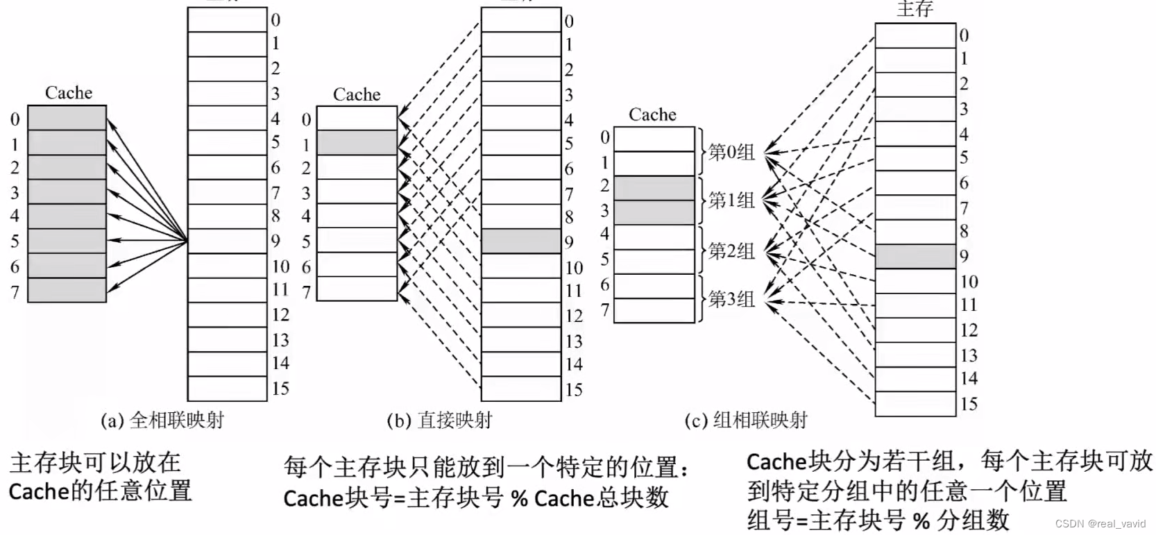
Associative Cache:
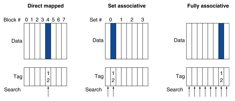
Fully associative
- Any block → Any cache entry
- All entries searched once (parallel)
- Comparator per entry (expensive)
n-way set associative
- $\left|S\right|=n$
- Block number % (number of sets in cache)
- All entries in given set searched once
- $n$ comparators needed
Kick out from associative cache: Random vs. LRU
LRU is simple for 2-way, managable for 4-way, too hard beyond that.
Multilevel Caches
Calc. single level cache architecture
memory access time → memory access cycles(miss penalty of L1) → effective CPI
Calc. two level cache architecture
hit + miss penalty of L1 + miss penalty of L2 = effective CPI
local miss ratio vs. global miss ratio
- L1: minimize hit time
- L2: minimize miss rate, avoid main memory access
- L1 with smaller block size than L2, smaller than a single cache
§5.4 Virtual Memory
Memory ⇋ Disk
Miss in virtual memory: access disk, otherwise access physical memory
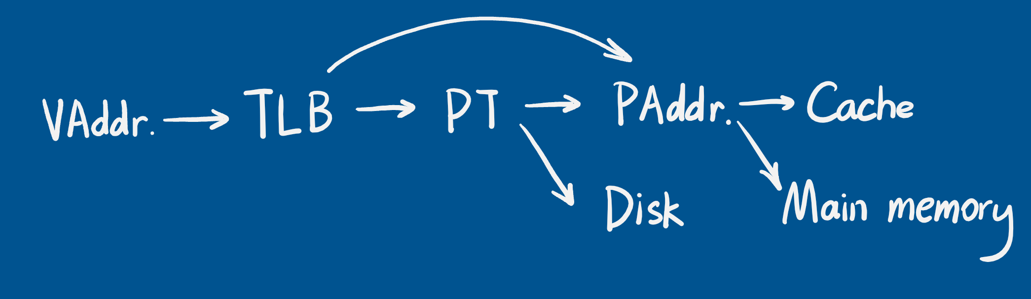
Address translation
|Virtual Page Number|Offset| → |Physical Page Number|Offset|
ptr → &Page table
Page hit
- Access page table, obtain the PPN and some status bits
- Access PPN
Page fault
- Access page table, raise page fault interrupt
- Fetch page from disk
Replacement and Writes:
LRU replacement:
- Reference bit in PTE, periodically cleared to 0 by OS
Disk writes:
- Write-back, write through toooo slow, dirty bit in PTE set when page is written.
Fast Translation Using TLB
TLB as “cache” of Page Table
TLB: |V|D|R|Tag|Payload|, Payload(PTE): |V|D|R|PPN|
Sources of misses:
- Compulsory misses (cold start misses)
- Increase block size to reduce
- Capacity misses
- Due to finite cache size
- e.g., try to put a block into a full cache
- Conflict misses (collision misses)
- In a non-fully associative entries in a set
- e.g., try to put a block into an already full set, but the cache is not full.
Cache Design Trade-offs:
| Design change | Effect on miss rate | Negative performance effect |
|---|---|---|
| Increase cache size | Reduce capacity misses | Increase access time |
| Increase associativity | Reduce confit misses | Complex hardware, increase access time |
| Increase block size | Reduce compulsory misses | Increase conflict misses and miss penalty |
§5.5 Dependable memory
Dependability measures:
Reliability: mean time to failure (MTTF)
Service interruption: mean time to repair (MTTR)
Mean time between failures: MTBF = MTTF + MTTR
Improving availability
- Increase MTTF: fault avoidance, fault tolerance, fault forecasting
- Reduce MTTR: fault detection, fault diagnosis, fault repair
Hamming SEC Code:
Hamming distance: minimum number of bits that are different between two valid bit patterns
Chapter 6 - Parallel Processors
§6.1 Introduction
Large, inefficient uni-processor → Small, efficient multi-processors
Scalability, availability, power efficiency
Instruction level: multiple issue
Data level: SIMD
Task level(process-level): high throughput for independent jobs
Parallel processing program: single program running on multiple processors
- Multicore microprocessors: Chips with multiple cores(GPU), SMP
H’ware: Parallel vs. Serial
S’ware: Concurrent vs. Sequential
Parallel programming difficulties
- Partitioning
- Coordination
- Communications overhead
Amdahl’s Law
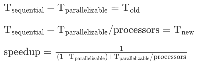
Strong scaling: fixed problem size, time is reverse proportional to number of processors
Weak scaling: constant time cost when problem size is proportional to number of processors
Load balancing
SIMD
- Operate on vectors of data: data level parallelism
Vector Processors
Multithreading
Coarse-grain multithreading
- Only switch on long stall
- Simplifies hardware, but doesn’t hide short stalls
Fine-grain multithreading
- Switch threads after each cycle
- Interleave instruction execution
- If one thread stalls, others are executed
Simultaneous Multithreading(SMT)
- In multiple-issue dynamically scheduled processor
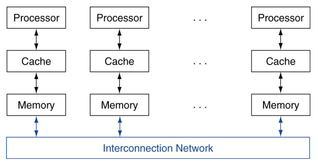
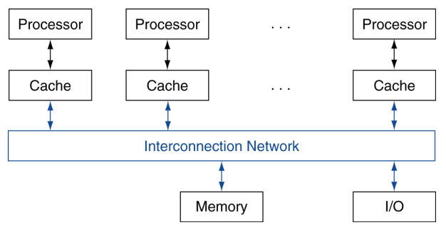
Shared Memory Multiprocessors
- All processors share one memory(uniform/non-uniform access speed)
Message Passing Multiprocessors
- Each processor has private physical address space