Outline
- Lecture 1: Introduction
- Lecture 2: STM32 MCU & GPIO
- Lecture 3: C for Embedded System
- Lecture 4: ARM Assembly
- Lecture 5: Interrupt
Lecture 2: STM32 MCU & GPIO
Recall
Value Notions: KMGTPEZ
Number System:
- Radix conversion
- Signed binary integers: signed magnitude, 1’s complement, 2’s complement
Computer Architecture: Von-Neumann, Harvard
Levels of Program Code: High, Assembly, Machine
Compiler, Assembler, Linker, Loader
Cross Compilation
Host: Cross compiler/assembler + linker/locator
Executable generated on host copied to target system
- Locator: For embedded systems, creates a file, containing binary image or other format, that will be copied onto target, which run on its own (not through loader)
CPU Overview
*Some knowledge about ARM series CPU
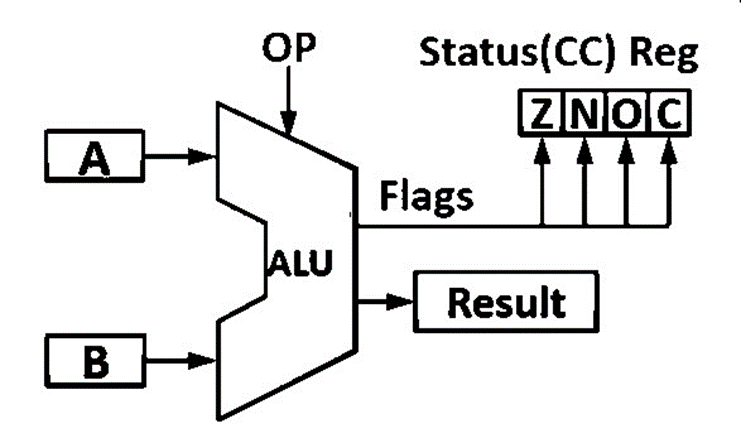
Arithmetic Logic Unit
- Flags: special bits providing info about the results
- Zero, Negative, Overflow (abbr. V), Carry

ALU Operands: register vs. data memory
Big/Little endian
Control Unit
- Decode the instructions to be executed
- Identify the dataflow
Program Counter etc.
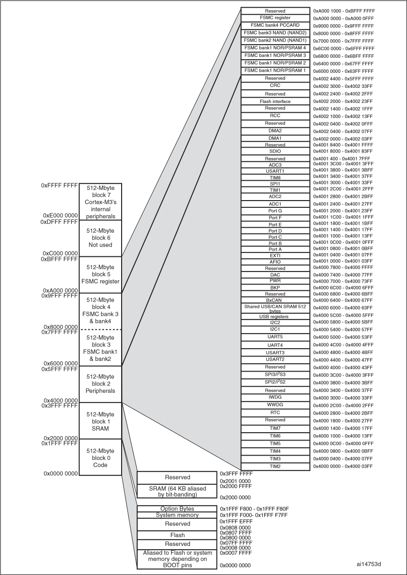
CPU Registers & Memory Map
0xF-Stack-Heap-Data-Code-0x0
See slides for the functions of CPU registers
Memory Mapped IO
Memory and IO device share address space, CPU treats IO device as memory

General Purpose Input Output
GPIO pins: Voltage control / Read / Write
16 * pins = port $\leftrightarrow$ register
Programming GPIO
- Enable the corresponding GPIO Clock
- RCC->APB2ENR (GPIO is on APB2 bus)
- Configure the GPIO Mode
- Setting CRL/CRH to configure input/output mode
- Each GPIO pin $\leftrightarrow$ MODEx + CNFx
- Set the output status if you are using GPIO as output
- Setting ODR to configure output status
- Read the input status if you are using GPIO as input
- Setting ODR (to configure input with Pull-up/Pull-Down)
- Reading from IDR (to get the input status)
Lecture 3: C for Embedded System
C related stuff is basic, so the note for this lecture is brief.
switch is faster than if-else when the number of branches is large.
Lecture 4: ARM Assembly
Mnemonic — Assembler —> Machine Code
In ARM mode, each inst. is 4-byte (32-bit) long. Cortex-M is Thumb-2 mode, inst. could be 16 or 32 bits long.
Program Status Register (PSR)

Negative bit
- N = 1 if most significant bit of result is 1
Zero bit
- Z = 1 if all bits of result are 0
Carry bit
- For unsigned addition, C = 1 if carry takes place
- For unsigned subtraction, C = 0 if borrow takes place (carry = not borrow)
- For shift/rotation, C = last bit shifted out
oVerflow bit
- V = 1 if adding 2 same-signed numbers produces a result with the opposite sign
- Positive + Positive = Negative
- Negative + negative = Positive
- Non-arithmetic operations does not touch V bit, such as MOV,AND,LSL
- V = 1 if adding 2 same-signed numbers produces a result with the opposite sign
Little-endian vs. Big-endian
Addressing Mode
- Register addressing
- Immediate addressing
- Immediate specified using 12 bits
<immediate> = imm[0:7]>>(2*imm[8:11])
- Indirect addressing
LDR r1, [r2,#12]- Pre-indexing:
LDR r1, [r2,#12]! - Post-indexing:
LDR r1, [r2],#12
Branch: if-else/loops
| Complex Instruction Set Computer | Complex Instruction Set Computer |
|---|---|
| Complicated CPU | Simple CPU |
| Each instruction takes longer to execute | Machine code instructions execute quickly |
| Fewer machine code instructions for each high level instruction | More machine code instructions for each high level instruction |
| Good code density | Poor code density |
| Smaller semantic gap | Larger semantic gap |
| Simple compiler | Complicated compiler |
Lecture 5: Interrupt
Subroutine
Branch and Link
Call a subroutine while saving the return address in the link register LR.
Branch and Exchange
Branch to an address specified in a register. The processor copies LR to PC after the program is finished.
Full Descending Stack (FILO)
- The bottom(base) is fixed at a particular memory address
- The top is identified by stack pointer register
SP
Call a subroutine
- Save current registers
CPSR,PC,LR,R12,R3,R2,R1, andR0to stack. - Update link register
LRto return address - Update program counter register
PC - Enter subroutine execution
- Restore registers in stack
Interrupt
Polling vs. Interrupt
Process a interrupt
- Finish processing current instruction.
- Save return address and register context to stack.
- Run interrupt service routine.
- Restore return address and register context from stack.
- Resume main program
Interrupt Service Routines (ISR)
- Subroutines to serve interrupts
- Invoked by hardware asynchronously (not controlled by program logic)
- Cortex-M: interrupt vector table, with pre-defined ISR addresses
Types of Interrupts
- Interrupts from peripherals modules
- External pin interrupts (
IRQ0toIRQ15) - Software interrupts
- Non Maskable interrupts (
Resetpin)
Interrupts are managed by Nested Vectored Interrupt Controller (NVIC)
- Program AIRCR register to set priority group
- Program IPRx register to set priority value
- Enable/Disable interrupts with ISER/ICER registers
Interrupt Priority
Types
- preempt priority
- sub-priority
- natural-priority (the priority within the interrupt vector table)
The smaller value, the higher priority
- Reset has highest priority